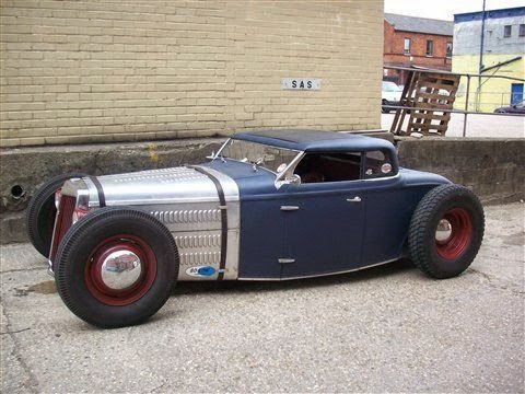
Thursday 25 December 2014

The Wheel Deal

Firstly, Merry Christmas to you, I hope you have a great day!
Yesterday I had my tyre guy come round, fit the tyres on my new wheels, give them a balance, and fit them on the T rod. Whilst they do fit the stud pattern, there is clearance, they will work great... once I have the correct wheel nuts. Sadly the original nuts will just end up eating their way into the wheels and I need to purchase some new nuts with a greater width taper to be able to fit them. I can't say I'm too pleased, but it's probably the best non-fitment scenario I could have came across. I wasn't able to get a decent idea of how they looked or how the car sat, it just would have damaged the wheels, but we did ensure that they'll fit and I'm sure they'll look great once they're on. When the nuts arrive you can be sure there'll be plenty of pics.
Have fun

Monday 22 December 2014

The Wheel Dilema cont.

Following a rather uneventful drive up to the M40 I met a very nice chap who I'd been messaging about his 5 on 5 Rocket Racing Strike wheels. There's no real story or drama here, the adventure was in no way adventurous, an easy drive there, a good honest seller, both of us were on time, the wheels and tyres were exactly as described, we put them in the boot, I handed over some monies for the amount we had agreed on, and away we went, everybody's happy. I just have to cross my fingers and hope that they fit as good as they look, the backspacing looks a bit larger than stated, but lets be honest, at the price I paid, I won't be complaining.

The Wheel Dilema

Pretty much every cookie cutter, traditional hot rod runs steels or, those all too familiar, 5 spokes. You know the ones; rounded, tapered towards the hub, generally highly polished or chromed. The Cragar SS, American Racing Torq Thrust type flavours, don't get me wrong they are lovely wheels, and look great, but I can't help but think I've seen them a few thousand times too many. For this reason, I instantly ruled out these wheels as even being a potential option for the T Rod, not to mention the astronomical price point, that would consume a large proportion of my budget in a heartbeat. I had my sights set on steels they fit both the budget and the overall style I have in mind for the build. I don't know whether I'd have made one good wheel out of two, have my current ones banded, or even have bought some generic modular wheels, but I was pretty sure I'd be running steels one way or another.

I can't remember exactly when I came across these wheels,I know they were advertised on Rods 'n' Sods Forum and that the advert was saved in my bookmarks, probably more as a point of reference than anything, but,  in all honesty that's no longer my concern, what really matters is that I found them, and with any luck they are soon to be mine.
I'm not holding my breath, I have a funny feeling that there might have been a typo on the agreed price, but that is the price that was agreed, so I've arranged to go and collect them tonight, I can only hope that there was no typo, and if there was, that the guy will stay true to his word and our agreement... only time will tell.


Friday 19 December 2014

The Insulation Installation

After dropping off my eldest for her last day of school I realised that I was having a fairly good day, and was relatively mobile, well, as mobile as I can be on a good day.
I hobbled down to the shed, slid my bar stool across the floor and started to unravel the insulation, luckily the roll is wide and the insulation is fairly sturdy, so it stood up on end unaided. With the aforementioned Screwfix order I bought a new stapler, I was going to use my hammer tacker, but the last time I used that to install insulation it broke through and ripped it, which isn't particularly useful. The new stapler is stunning, and very easy on the fingers, especially seeing as you can basically just lean on it and it shoots the staple.
Anyways... I was sitting on my barstool and unrolling the insulation, with the thickness of this stuff it made it really easy to work with, I just squared it up to the wall and popped some staples into the baton, stretched it a little then shot some more staples, I haven't put any in the bottom half, because I just cant get down there and be able to get back up again, but I should have a friend coming over Christmas Eve that I may be able to convince to play with a "stapley toy" for a little bit and get that sorted. Even at my speed I managed to a reasonable amount of it done before I had to stop and go sit in my chair, its a hell of a lot easier to work with than any other form of insulation that I have used in the past, performance dependant, I'd recommend it to anyone and everyone.

Reserved space for when I put some pics up tomorrow... if I can make it down the garden and back again :)

I really haven't posted enough pics over the last few days, I'll have to get on that, theres been far too much writing and not enough to look at, sorry.

Thursday 18 December 2014

Let There be Light... in the Shed

After much deliberation, I decided on which flavour of insulation and lighting I'd be using in the new shed. Due to space restrictions I will be using Airtec Double Insulation, heavy duty bubble wrap covered in tin foil both sides, supposedly this stuff has the same thermal efficiency as 2" polystyrene. Even if its half as good as what the manufacturer states, it'll be more than sufficient, and if nothing else will almost put an end to most, if not all, of the draughts. When it came to the lighting, I ordered a 5ft long 58 watt weatherproof bayonet (strip light) which came with the tube and light diffuser. There may well be more lighting installed at a later date over the work bench as the far ends of the shed are a little dark, not like dark dark, but enough for me to think that it might be best for it to be a little brighter, we'll see...
This evening I sat in my recliner, in the warm and wired up the light, for the mean time I have simply fitted a plug to the end of the wiring and have it running off of an extension lead running from its own fuse in the main shed, sure its a bit ghetto, but, its light so I'm not complaining.
This was the first time I have every ordered from Screwfix for home delivery, to my surprise their delivery service is exactly as advertised and I received my items in under 24 hours from placing my order, needless to say, once I have decided on what's living where, the location of the workbenches and shelving etc, I will be ordering all the rest of the electrical stuff from there.

Tuesday 16 December 2014

Wheels Wheels and More Wheels

Since my first drive of the T I knew it needs more meat in the back even with the little 3.5 litre Rover motor it doesn't hook up very well, and that's just on the street and without going full throttle. The rear tyres are skinny, hard, old and not very tall so not the best examples to start with and are pretty much everything you don't want from a tyre on your hot rod.
Sadly who ever built the car originally used a narrowed Volvo axle in the rear, but really its a bit too narrow, there are already witness marks on the pick up bed from the current 4" wheels. They have around 3 1/2 - 4" of backspace which is a fair amount on a 4" narrow rim, whatever wheel and tire combination I settle on, there must be a maximum of  3" of wheel/tyre hanging off the back. Seeing as I am looking for 8+ inch in width its near impossible to find a wheel off the shelf with such a huge amount of negative offset.
Its looking like my only option is to make some custom wheels, which will probably end up at around 7" to negate the overly narrowed axle and tyre rubbing but should still significantly improve traction.

I realise that wheel terminology can be confusing at best this image clearly shows all of the jargon you need to understand to select the wheels for your rod.


You will see offset stated as ET on most factory and after market wheels. The positive and negative ET are measured in mm. ET may seem a strange way to abbreviate offset, but it is actually an abbreviation of the German word, "Einpresstiefe" the literal modern day translation being offset, why a German abbreviation is used on wheels I do not know, though purely out of interest I may do some research and find out the reasoning behind this standardisation.
Similarly you will often see wheel width measured with the suffix J. J is not used to identify the measurement of width, it is informing you of the wheel cross section, the shape of the bead seat and is a global standardisation for tyres and rims to ensure that all tyres and rims of the correct sizing are both safe and compatible.

Should I come across any further information regarding wheels and this associated jargon, I'll add it to this post.

Sunday 14 December 2014

Love at First Sight - Street Altered Style T Bucket

Following such a strenuous day I have been napping and reclining in my comfy chair glued to my lap top and  consequentially fell in love all over again with this;


Incredibly angry altered street styled Model T bucket with a great stance, even though its probably not actually drivable at its current ride height with the front of the chassis sitting about 2" off the floor. This one has really got me thinking.

Tool shed

Today was a good day, my tool shed has been completed! One of my mates very kindly offered to come over and finish my shed roofing. My stunning contributions consisted of playing the vital roles of head tea boy, chief pressure washer operative and site supervisor... more commonly known as making a few cups of coffee, sitting around pressure washing the roofing sheets and sitting around some more.
Hopefully in time I'll be able to collate my tools and anything else I deem vital to keep in the dry and start filling the shed eventually realising that I should have bought a bigger shed and kicking myself.
Huge thanks go to Lee and Laura for all of their help!

Pics to follow....

Wednesday 10 December 2014

1/4 Elliptical Front Suspension

After around 18 hours of research, looking at pictures, reading every tech article and forum entry I could find, I have found an ideal design for the quarter elliptical suspension that I will be using on my T.


Photos and craftsmanship courtesy of Kardude67 from the infamous H.A.M.B. Jalopy Journal forums

There we have it!! An absolutely stunning piece of engineering and design, it should even work just as good as it looks. From what I can see the builder has scratch built the upper links and the awesome spring/link mount located on the original U bolt holes on the old parallel leaf spring pads, not to mention those speed holed frame rails and lovely curvy cross member. It look as though there is a height adjustment bolt fitted through the top of the rail a la Posies 1/4 spring kit, there is also a horizontal bolt, that could well be through a spring eye, or possibly a through some machined solid stock with the bolt acting as a locator. However he has chose to do it, it doesn't change the fact that it is an incredibly aesthetically pleasing set up, and a true credit to his work

1960 Ford F100 Front Axle

I was chilling out last night, cruising around on the net, ropey reality TV car shows in the back ground, a pretty standard evening for me. As always I was searching the usual sites classifieds for cheap parts, inspiration, boobs etc.
I came across a chap, not literally of course, that had just finished a Jag IFS conversion on his '60 F100 and had a post up on a Facespace page offering the remaining parts, "if anyone can make use of them"

"Sorry for the bad pic. I have a 1960 Ford f100 front axle
and a few oddments available if anyone can make use
 of them. Message me if interested thanks"


After messaging a couple of buddies and chewing fat about possibilities, design concepts, and suspension options I started the usual lengthy process of "instant" messaging to procure said parts. I decided to make an offer on the entire font axle assembly and the rear leaf springs to allow me to assemble and adjust a suitable set of leafs suited to the T.
During the course of the evening/early morning I have set my sights on building the solid axle with a 1/4 elliptical leaf spring, the shock and attachment details are yet to be decided upon, but are in the mix.

Tuesday 9 December 2014

Home Made Engine Leveller Plans


Materials:

Beam
40x40 box section, 450mm long

Saddle
2 off 50x50x6 angle, 80mm long or box section that is a good fit on beam

Hoop
10mm round or square bar, 200mm long

Handle
25 x 5 strip, 100mm long
12mm round bar, 60mm long
End plates Bitmap image DXF drawing 2 off 80 x 6 strip, 85mm long


Threaded bar
M16 threaded bar, 500mm long
3 off M16 nuts

Full drawing:

Construction:
Wrap a couple of layers of thick paper or one layer of thin card around the beam. Place the two pieces of angle over the wrapped bar to form a box section. They will form the saddle. You will need to grind the edges of the angle where they meet to make them a tight fit on the beam. Tack weld the two pieces of angle together and slide them off the box. Remove the paper and check the saddle slides easily on the beam without too much play. Fully weld the pieces together and check again.

Mark out one end plate, clamp the two together and drill the 13mm and 16mm holes.

Place one end plate flat on a heat proof surface. Slide the saddle over the box and place them on the plate. Screw one of the nuts approx 45mm on to the threaded bar and place the threaded bar in the 16mm hole, with the nut touching the saddle. Place the other end plate on top of the assembly to hold it together. Placing a weight on top helps stability. Another pair of hands are useful at this stage. Tack weld the nut to the saddle. Turn the threaded bar until the saddle is approx 10mm off the lower end plate and tack weld the box section to the end plate. Wind the saddle to the other end of the bar, turn the assembly upside down and tack weld the box to the end plate. Check the saddle winds forwards and back easily with no binding then fully weld the nut and end plates.

Bend the 10mm bar into a hoop that will fit over the saddle and tack weld it on. Check the hook on your engine hoist will sit comfortably in the hoop then fully weld it.

Drill the 16mm hole in the handle and bend it as shown in the diagram. Place a washer over one end of the threaded bar then fit the handle and weld it on to the bar. Weld the 12mm bar on to form the complete handle.

Fit a washer on the other end of the bar and screw the other two nuts on. Lock the nuts together, making sure the bar is free to turn. Grease the moving parts and your balancer is ready to go.

Note: do not paint the beam as the saddle will tend to bind, especially when under load.

To use the balancer hook it onto your engine hoist, then attach lifting ropes or chains to the front and back of the engine. Use shackles to attach the lifting ropes/chains to the 13mm holes and start lifting. As you start lifting you will have to move the saddle until you find the balance point.

Note: Most of the dimensions can be altered to suit available materials. For instance you may be able to find some box that is a tight fit over the beam to make the saddle, or you could use a different thread on the threaded bar. The only real problem with a smaller thread is that it takes longer to adjust the balancer. Don't go less than M12 or it will be too weak.

Copyright 2000 by Les Newell

Sheet Metal Bending Brake

How to make a home made sheet metal bending brake

Cut all the metal pieces to size (don't drill any holes yet, though), then take the two hinge leaf sections and round one end of each to make a 3/8" radius. Drill a 5/64" hole on the point of this radius, and weld the hinge leaves to the ends of the base (the centres of the bores in the leaves should line up exactly with the outside corners of the angle-iron base). Next, cut the notches indicated in the pivot block, and clamp it to the front of the base...so that the top surfaces of the two components are flush. Then, drill a 5/64" hole on centre and 1/2" from the end of both handle pieces, temporarily fasten these 3/8" X 1" X 9" bars to the hinge leaves by running a small finishing nail through the two pairs of holes, and-finally-weld the pivot block to the two handles...taking care not to include the base in your weld. With that done, remove the two finishing-nail hinge pins, enlarge the holes in your "double-thick" hinges to 1/4", loosen the clamps, and set the entire handle assembly aside till later. Now bore a 13/32" hole in each end of the hold-down bar (1" from the extreme edges and 1/2" from the angles inside fillet), followed by another hole...of the same size but 5/8" in front of the first. Continue drilling to remove the "meat" between each pair of holes until a rough slot is formed, then take a small file and shave the edges of the slot till the opening forms a smooth, elongated oval. Following this, grind a 45 degree bevel on the hold-down bar's forward edge, then carefully level the grind with a flat file. Next, clamp the hold-down bar to the base (with the bar's bevelled edge 1/16" from the "point of bend") and mark a spot (3/16" from the "inside-fillet" edge of the slot) on the upper surface of each end of the base. Remove the clamps, then drill a 7/16" hole at each of the two points. Now slip 3/8" bolts into these holes from the angle's underside, and weld the heads in place. Once the bolts are firmly attached, drill a 13/16" hole in both adjusting bolt guides, thread the bores with a 1/4" tap, and weld the pieces to the base-directly behind the 3/8" bolts- as illustrated. You can also take this opportunity to permanently fasten the handle assembly to the base by fitting the 1/4" X 1" hinge pins into the holes and tacking the protruding "stubs" to the handles. With all the components completed, give your brake a coat of rustproof paint, and-when it dries- thread the wing nuts onto the eye bolts, screw the eye bolts into the adjusting bolt guides, slip the hold-down bar over the 3/8" bolts (keeping it in place with the two hex nuts), and install the handle grips. Then just clamp the lower lip of the brake's base in a vise...and you are ready to bend some metal!


Sympathetically edited from: The Mother Earth News magazine No. 56 March/April 1979

Solid Axle Disc Info

Ford Popular 103e Solid Axle Disc Conversion

Ford Anglia 105e hubs to fit Ford Popular 103e spindle; Inner hub bearings are available that are a mix of the Pop spindle outer diameter and the Anglia 105e hub outer diameter these bearings allow you to fit a 105e hub to the 103e spindle. The part number for this bearing is 07098 07210X and should be avaliable from any bearing supplier for around £17.50 each.
Outer hub bearings are interchangeable between the 105e and the 103e.

What Tyre Size on Rim

Select your rim width, the table will then tell you what width tyre to go for, for the width of your rim:


Monday 8 December 2014

Shiny T

Found this highly polished rod whilst cruising around the net last night, a little too shiny for me, I'd be scared of driving it in that condition, but the use of numerous metal finishing techniques, traditional colour and complimenting interior do get the cogs turning.


My Model T RPU

After a 200 mile trip, with a few stops, cold toes fingers and nose and a stupid grin on my face, my new T RPU is home!  Here's a few pics with the hood/tent up, not the best contraption and incredibly noisy with it slapping around all over the place, but should it have rained, I'd have been dry, so I'm not going to complain too much.


How to Set up Weber 38 DGAS


From: www.redlineweber.com

Pull in at Inspiration Station

I've been collecting images of various builds for inspiration as to how I should go about finishing my car


BW-66 Auto Box Repair

BW-66 Delayed Upshifts Solved
Dan Jensen

I had previously mentioned that the BW-66 in my '81 XJ6 would not upshift from 1st to 2nd when cold. Only after driving ~1/2 mile would it finally shift, and then almost immediately into 3rd and would then not downshift without the use of the shift lever. After the engine/transmission warmed up, the transmission operated as expected. These symptons seemed to indicate a sticky governor.

I pulled the governor last night to examine and clean it. [NOTE: there is a right way and wrong way to install the governor on the ourput shaft (learned this the hard way last year). Carefully note which side is rearward, i.e., the side with the opening faces to the rear.] There was no significant wear, but the flyweight action was sticky, requiring that it be pushed lightly by hand to get it to move. I disassembled all components of the governor, carefully cleaned them with clean Type FA ATF and a lint-free rag, and reassembled them. After assembly, gravity at ~45o was sufficent to cause the flyweight to move. After reinstalling, the transmission now shifts normally. The clearances on the governor sliding surfaces are very tight and an essentially imperceptible piece of grit most likely was retarding the free movement of the flyweight.

The task took about 3 hours, but I have done related transmission work on all my Jags so I am perhaps a bit faster than the usual shade tree mechanic. The only special tools I used were my self-designed wood beam engine support and a short wood 2" x 4" with a hole drilled in the middle to allow easy removal and installation of the rear motor mount with my floor jack.

B. J. Kroppe says:

Great post. Did you have to undo the spring tension on the rear transmission mount? When I installed my rear mount on the transmission (out of the car) last summer, it was a bear, and not fun.

Any good tips on how to wrestle with this?

The following is a description I have sent to two other interested parties re my governor repair. As far a replacing the rear mount, it is very easy if you use a floor jack and a short 2x4 with a hole in the center to raise the mount to the underbody. This way it is a breeze. I have tried it the other, i.e., manual, way and yes it is a bear. Peter Hamel wanted to know if he could do this job in the street. My response includes this question.

Let me start off with a recommendation. Ignore this if it does not apply to you. Buy a copy of (1) the factory repair manual, (2) factory parts manual, and (3) factory wiring diagrams. If you own a Jag and plan to do much of your own work, you will use all of these many times. Each can be purchased from the aftermarket. Total cost might be $100-150, but you will save that many times over. The Haynes manual is definitely not a substitute for any of these. In fact, I never open my Haynes manual. The reasons you should buy these are (1) the factory manual describes how to remove the governor (and many other useful things), if somewhat cryptically, (2) the parts book shows a blowup of the governor, how it should be positioned, accompanying bolts, seals, etc., and (3) well, this is a Lucas-equipped car. But on to your question. The following is my recollection of last night's work and the 4 or 5 other times I have worked on transmissions in my Jags, but use your eyes and judgment as you proceed since I may have missed a step. 


  1. You need to jack the car up high enough to crawl around underneath. I use four tall jack stands and a good size floor jack to raise the car about a foot. Sometimes it is a bit tough to roll a floor jack on street surfaces, but you will have to be the judge of that.
  2. You need to perform the following steps once the car is up on jack stands
    • a. Put the transmission in neutral. Loosen dipstick tube upper retaining bolt near dipstick and exhaust manifold.
    • b. Loosen disptick tube at pan and drain the fluid. This will be ~2-3 quarts. In theory, it may be possible to avoid this step if the front of the car is lower than the rear, but it is so easy to drain, I suggest you drain it. Besides, you will want to get as much of the old fluid out as possible and several fill and drain cycles will be required to get down to <~15% old fluid.
    • c. Remove three bolts securing exhaust pipe to catalyst.
    • d. Remove exhaust pipe heat shield on left-hand side of car (Phillips-head screws)
    • e. Remove 3/4 in. nut holding rear bracket to rear mount.
    • f. Remove two nuts securing rear bracket to transmission case
    • g. Remove the nut securing the shift lever to the transmission manual valve adjuster. Remove bolt securing shift cable to transmission bracket.
    • h. Support engine, either by a support in the engine compartment (you might as well make one of these for $20. Believe me, you'll use it again) or by putting a second jack and 2x4 beneath engine pan.
    • i. Remove four bolts securing rear mount. The mount is spring loaded so it is best to support it with your floor jack and lower it after all the bolts are loose.
    • j. Remove the eight bolts securing the rear motor mount support plate to the body.
    • k. Remove the four bolts/nuts holding the propeller shaft to the transmission output shaft.
    • l. Put the transmission in park by using a adjustable jaw wrench to turn the manual valve adjsuter. Remove the 3/4" bolt from output shaft and remove the output shaft flange.
    • m. Disconnect the speedometer cable and remove the drive gear bracket and drive gear.
    • n. Lower the engine somewhat at the engine support or jack, and start removing bolts from transmission tail housing. Note that some of the bolts are 9/16 and some are 12 mm (I think these are the correct sizes). The 12 mm bolts require a 12-point socket. A 6-point socket will not work. Note the location of each bolt since there are three different types of bolts securing the tail housing.
    • o. When all bolts are loose, tap housing. It should pop free. Once it is off, you will see the governor.
    • p. Note it's position (as mentioned earlier, it can go on backwards and I guarantee your car won't shift out of first, ever - guess how I found out?) and loosen the large bolt on top a few turns to slide the governor off.
    • q. If working o.k., the flyweight should easily slide back and forth in the sleeve as you tip the governor. If there is any binding, you need to dissassemble the governor and clean it carefully. This is easily done. Be careful. Even a slight bit of lint can land you right back where you are now.
  3. As you may have inferred, a picture is worth a 1000 words. I personnally would hold off on this until you had (1) and (2) above. On a scale of 1 (add fluid) to 10 (do your own transmission rebuild) this is about a 3-4.

From: www.jag-lovers.org